Camshaft position sensor test
Checking the camshaft position sensor (CMP) allows for verifying its functionality and correct functioning. From the symptoms of malfunction, you can see the total failure of the sensor or its unstable operation, and for an accurate diagnosis you need a multimeter or diagnostic scanner. As a rule, the sensor itself rarely fails, but its wiring and plug require attention.
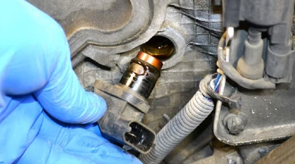
Location of the camshaft position sensor on the engine
To check the camshaft position sensor, you need to know where it is located. Typically, on eight-valve engines, the camshaft position sensor is normally mounted in the end of the cylinder head. On sixteen valve engines, it is also mounted on the cylinder head, usually in close proximity to the first cylinder.
Symptoms of a bad camshaft position sensor
If the camshaft sensor fails (the electronic control unit receives incorrect information from it or does not receive it at all), the switch to the emergency mode is programmed. It implies using pairwise-parallel (group) fuel supply to the engine. This leads to two negative consequences:
- A slight loss of engine power, especially when driving in critical modes (acceleration, driving under load).
- Increase in fuel consumption by about 10...20 % (depends on the engine power, its design features, as well as the operating conditions).
As for diesel engines, the sensors of camshaft position are arranged similarly, but there is one difference. It consists in the fact that the sensor fixes the position of not only the first cylinder, but all cylinders. This is done due to the fact that there is a separate tooth for each cylinder on the target disc.
Thus, you can notice the sensor failure by the change in the operation of the car engine, as well as some other symptoms.

4 Sign of a bad camshaft position sensor or failing symptoms codes: video
- Having to twist the starter motor longer when starting the engine.
- Unstable operation of the engine, engine hunting and idling revolutions of the engine.
- «Slumps» in the car movement, when you press the accelerator pedal it does not respond immediately, the dynamic characteristics of the car are lost (accelerates weakly, does not pull, especially in a loaded state and when driving uphill).
- When resetting the accelerator pedal, the engine stalls.
- Fuel consumption is increased (by 10...20%).
- Check Engine signal lamp on the dashboard is activated. Typical error codes (when diagnosed with the scanner) concerning the work of the sensor have numbers P0340, P0342, P0343.
How to check camshaft position sensor
Before you check the sensor with a multimeter or other electronic devices, you need to check it visually. Namely, the integrity of the sensor housing, presence of cracks or other damages. It is also desirable to check the guide disc for damaged teeth and for metal shavings on or near the sensor body.
There are two basic ways to check camshaft position sensor — with an electronic multimeter and with an oscilloscope. The first method is easier and faster, but the second is more accurate and gives more diagnostic information. But it is not worth to check with a metal object for the presence of magnetic properties, non-working camshaft position sensor can also be magnetic as well as serviceable one.
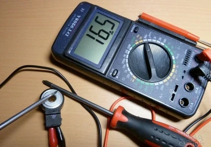
How to test a camshaft position sensor with a multimeter
To test it is necessary to measure the voltage of a camshaft position sensor that is generated on its signal wire. The data you get will depend on the sensor type and the vehicle model. Also, note that depending on the type of sensor it will have a different number of pins. A magnetic or inductive type sensor has two wires, and a hall effect camshaft position sensor has three wires. You should also check the continuity of the wires. You will need a multimeter in DC and AC (for double pin) modes for diagnosis.
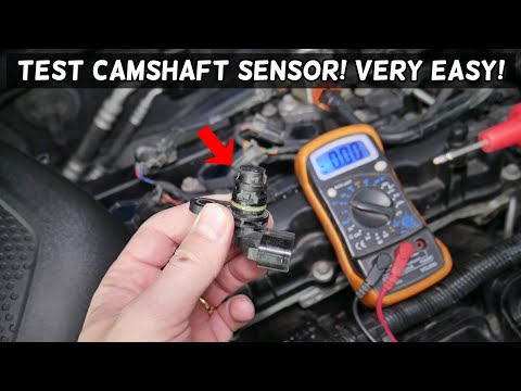
How to test camshaft position sensor on a car: video
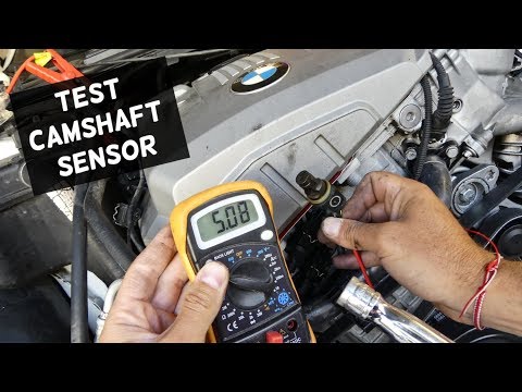
Test camshaft position sensor on BMW: video
Before you start the test, you should put the box in neutral (for manual) or in park (for automatic), put the car on the parking brake, and also disconnect the fuel system by pulling the fuel pump jumper from the fuse block to prevent engine starting. Then find out which sensor pin is responsible for what.
Camshaft position sensor testing 3 wire
Camshaft position sensor testing 3 wire
- Set the DC volts mode on the multimeter and disconnect the sensor connector;
- connect the red probe to the power lead and the black probe to the battery minus;
- ask your partner to try to start the engine for a few seconds;
- the voltage reading on the gauge should be about 5 volts (this is how you determine both the integrity of the power lead and whether it is powered);
- to find out if the minus wire of the sensor connector is intact and short-circuited, connect the red dipstick to it, and keep the black one on the negative terminal of the battery;
- ask your helper to crank the engine again, while looking at the multimeter screen, the voltage reading should be 0.1 or 0.2V;
- repeat the same procedure only with the signal wire, only this time the voltage on the screen should vary from 0 to 5 volts (if it is good);
- without starting the engine, but only with the ignition on, measure the voltage between the plus and signal contacts. It must be at least 90% of the supply voltage.
How to test 2 wire camshaft position sensor
Check one by one that the wires are intact and that the connector is working. To check the inductive type (most often installed on older cars) use several methods: check if there is voltage from the signal wire during operation, and if the sensor generates its own AC signal.
To check the power supply of the crankshaft sensor of magnetic type it is necessary:
Camshaft position sensor testing 2 wire
- disconnect the connector from the CMP sensor;
- set the multimeter to 20V DC voltage mode;
- turn on the ignition (but do not start the engine);
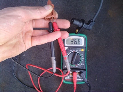
- connect the red probe of the digital multimeter to the signal wire (blue as a rule) and the black to the minus terminal on the battery;
- the signal received by the digital multimeter on the display should be close to 1.5V (but the exact value can only be found in the repair manual of the particular car).
- To check if there is a break in the ground wire, set the switch of the multimeter to the test mode;
- connect the red probe of the multimeter to the second terminal of the chip and the black probe to the minus terminal of the battery — a beep indicates the integrity of the wiring.
- set the DMM to AC voltage mode;
- connect the probes to the leads on the sensor;
- start the engine for a few seconds (ask for help) to see if there are any readings on the multimeter.
If the sensor is removed, you can do another test in AC volts mode. Bring a metal object to the end of the sensor (its signal part). Re-measure the voltage at the signal contact. It should not be more than 0,4V. If the plate is removed then the voltage should be restored to 90...100% of the supply voltage.
If there are any deviations in the process of testing it means that the sensor is out of order and must be replaced.
Besides voltage of CMP sensor of magnetic type it is possible to check resistance on its coil. To do this, set the multimeter to Ohm mode and measure the resistance on the sensor pins (you do not need to dismantle it). On some models, the resistance value must be in the range of 200 — 900 ohms (the exact value must be seen in the manual or specifications of the sensor). The main thing is that the resistance does not tend to infinity, so it will indicate a breakage of the winding and it is definitely subject to replacement.
Checking the CMP sensor with an oscilloscope

Checking the CMP sensor with an oscilloscope
An electronic oscilloscope helps to understand how the camshaft position sensor works and whether it produces pulses. There are both special diagnostic devices and simulators, which are laptop or smartphone programs, and the connection is made by connecting the diagnostic scanner to the connector OBD-2.
The oscillogram of the camshaft sensor should be an even chart with one dropping out peak, which corresponds to the passage of the rapper through the sensor. So, when you check the magnetic sensor, there should be a sinusoid, and when you check the sensor on the Hall effect, the digital signal will be square with the points of highest and lowest voltage. If it has a different shape, an additional check is needed.
When diagnosing the camshaft sensor of «Nissan» cars (in particular, Nissan Almera) with an oscilloscope, the shape of the oscillogram will be different. It will not be flat, but in the form of 3 pulses, then a space, then 4 pulses — a space, 2 pulses — a space and one pulse — a space. This peculiarity is the norm for the engines of this automobile manufacturer.
