Repairs of Valeo 90A electric generator
Works, carried out on Valeo 90A electric generator:
- replacement of brushes
- replacement of bearings
- replacement of the slip ring assembly
Tools used:
- hammer
- big bearing remover
- small bearing remover
- solderer
- file
Spare parts: FAG 6202.2RSR and FAG 6303.2RSR bearings

Bearing
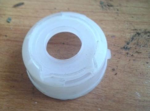
CARGO 135508 electric generator bearing spacer
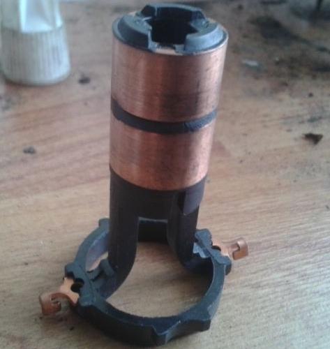
CARGO 230090 slip ring assembly
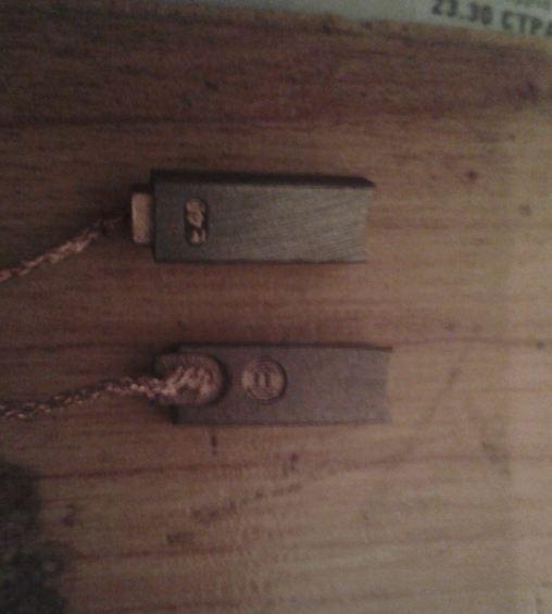
BOSCH 1 127 014 022 generator brushes
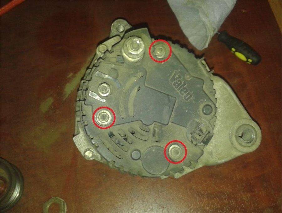
Remove the generator cover by unscrewing three nuts with the wrench for 8
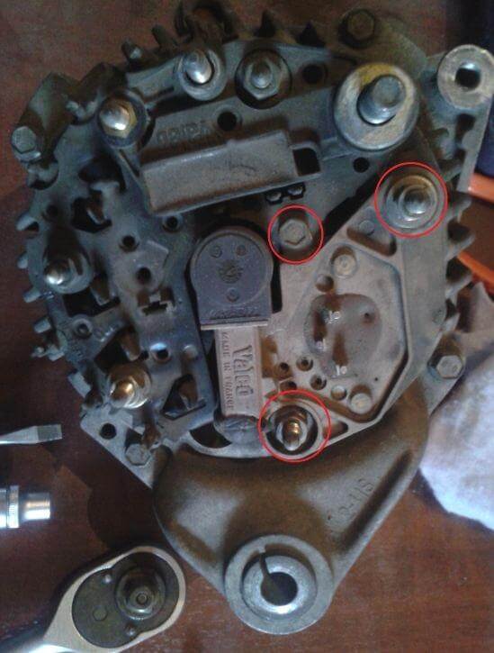
Remove the regulating relay by unscrewing two nuts with the wrench for 8 and one bolt with the wrench for 7
Remove the cover that protects the brush assembly and check out the state of the brushes...

Next objective is to dismantle the diode bridge. On this type of generators it is soldered up to the stator winding leads, so, in order to separate winding leads from the diode bridge (6 pcs.), you will need sharp side-cutting pliers
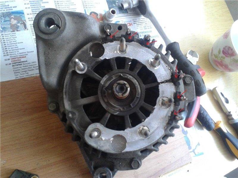
Remove the diode bridge by unscrewing four nuts with the wrench for 8. Then, take out six plastic insulators from the stator leads
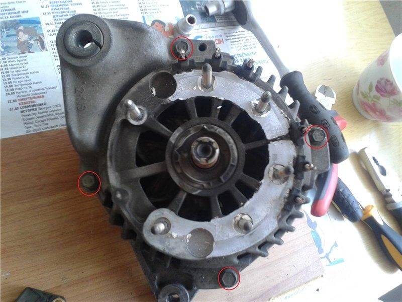
Unscrew four bolts with the wrench for 8
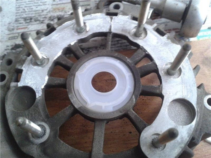
Remove the top part of the generator, clean it up and replace the bearing spacer with the new one

Press out the rotor from the generator housing using a bearing remover. Unscrew four bolts in the bearing cover with the wrench for 8 and replace the bearing with the new one (for screwing up the bearing cover I used a thread locker)

Using a small bearing remover remove the second bearing
Gently clean the plastic insert from resin and remove it
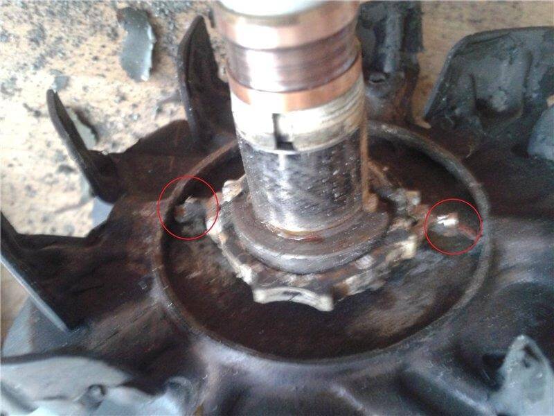
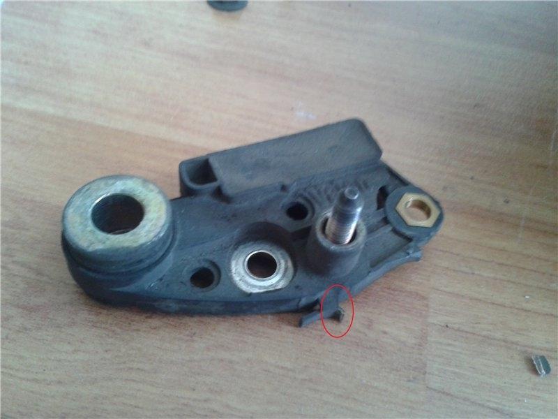
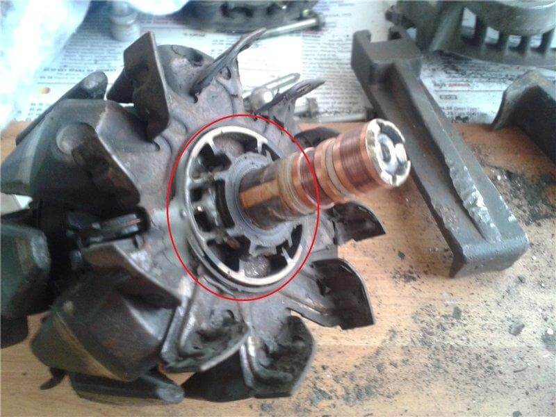
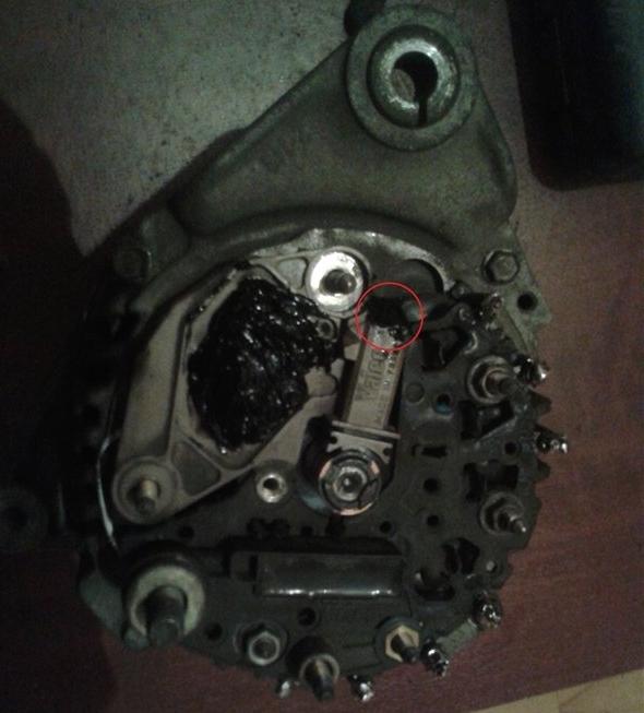
Remove the epoxy resin completely without damaging the couplings (marked with red) of the slip ring assembly with rotor winding
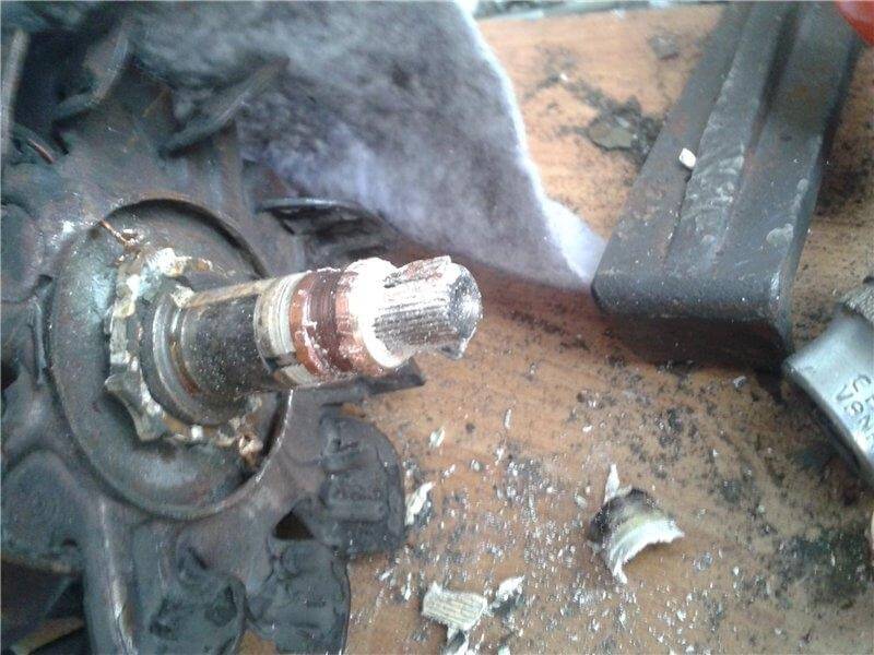
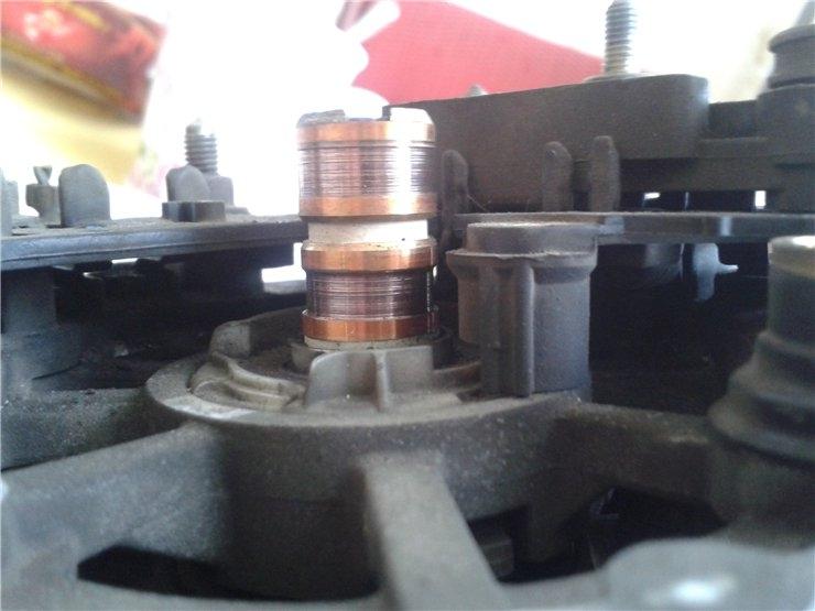
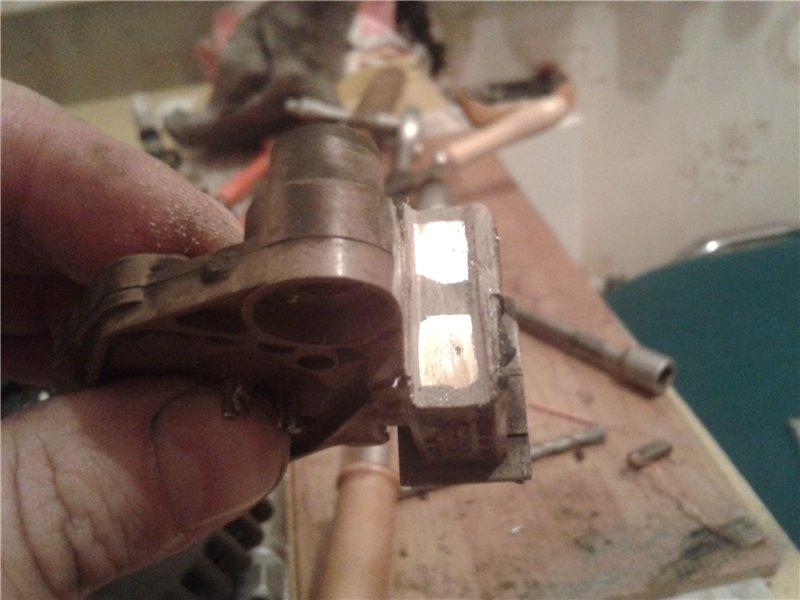
With a sharp knife release couplings of the slip ring assembly with rotor winding and destroy the collector (I used a hacksaw)
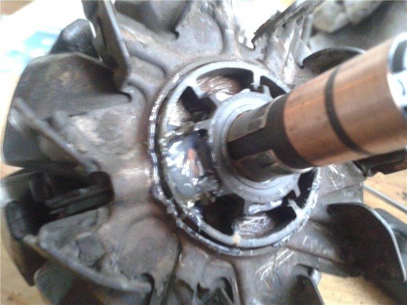
Press up a new collector, connect and solder thoroughly contacts of the slip ring assembly and rotor winding. Pour over the contacts with Poxypol (clear) and install the insert… use Poxypol again to patch up cavities even with the contacts
Press up the second new bearing onto the rotor and assemble the generator. During the diode bridge installation I used the thermal paste. Solder thoroughly the couplings of diode bridge with stator winding (using a copper wire).
Replace the brushes
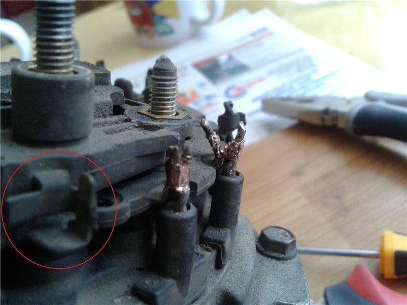
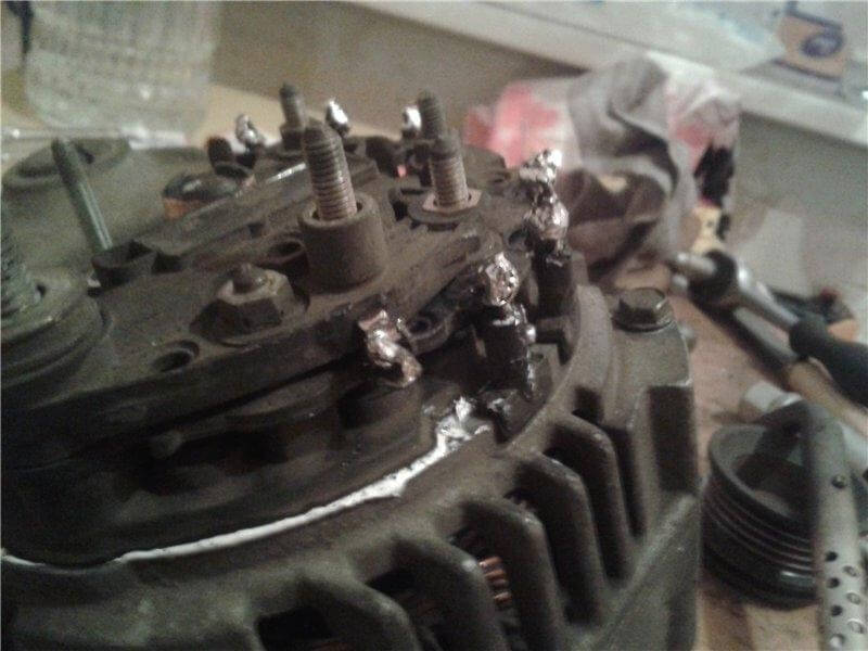
Solder the brushes in and apply some sealant at the contact points (marked with red). I patched up the regulating relay contacts with the same sealant
